


What Are the Most Common CNC Machining Problems and How Can They Be Diagnosed?
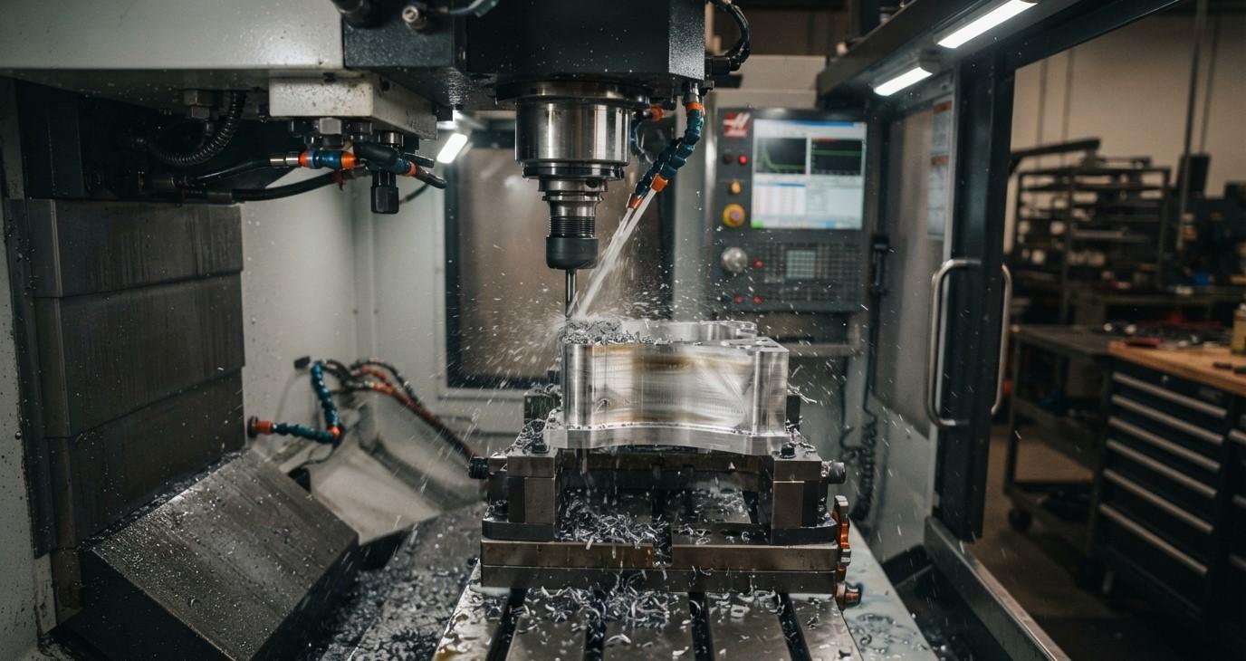
CNC machining provides excellent accuracy, repeatability, and productivity, but even well-maintained CNC machines can experience machining problems. Issues such as poor surface finish, dimensional errors, tool breakage, chatter, burrs, excessive tool wear, and incorrect hole sizes can affect production quality and increase costs.
The key to solving these problems is proper diagnosis. Instead of changing several machining parameters at the same time, machinists should identify the visible symptom, inspect the cutting tool and setup, check the machine condition, review cutting parameters, and then make controlled adjustments.
For workshops and manufacturing facilities, selecting suitable tooling and maintaining the machining system properly can prevent many common problems. Khokhawala Trading LLC, an experienced Industrial Tools Supplier in Dubai, supports industrial businesses with tools and equipment used in machining, cutting, drilling, measurement, and workshop applications.
This guide explains some of the most common CNC machining problems, their possible causes, and practical ways to diagnose them.
Table of Contents
-
Why CNC Machining Problems Occur
-
Poor Surface Finish
-
Dimensional Inaccuracy
-
Tool Wear and Premature Tool Failure
-
Chatter and Vibration
-
Burr Formation
-
Tool Breakage
-
Oversized or Undersized Holes
-
Poor Chip Control
-
Excessive Heat During Machining
-
How to Diagnose CNC Machining Problems
-
CNC Problem Diagnosis Table
-
Frequently Asked Questions
-
Conclusion and CTA
Why CNC Machining Problems Occur
CNC machining problems rarely have only one possible cause. The cutting tool, workpiece, machine, tool holder, workholding system, coolant, programming, and cutting parameters all interact during machining.
Common causes include:
-
Incorrect cutting speed
-
Incorrect feed rate
-
Excessive depth of cut
-
Worn or damaged tools
-
Incorrect tool geometry
-
Excessive tool overhang
-
Tool runout
-
Poor workholding
-
Machine vibration
-
Incorrect tool offsets
-
Poor chip evacuation
-
Inadequate coolant
-
Programming errors
-
Thermal expansion
-
Improper machine maintenance
A systematic troubleshooting process helps identify the actual root cause instead of treating only the visible symptom.
Poor Surface Finish
Poor surface finish is one of the most common CNC machining problems. A finished surface may appear rough, wavy, scratched, smeared, or covered with repeating tool marks.
Common Causes
Poor surface finish can result from:
-
Dull or worn cutting tools
-
Incorrect feed rate
-
Incorrect cutting speed
-
Chatter
-
Excessive tool overhang
-
Tool runout
-
Poor workpiece rigidity
-
Incorrect tool geometry
-
Inadequate coolant
-
Poor finishing toolpath
Regular repeating marks are often associated with vibration or chatter, while rubbing, smearing, or inconsistent marks may indicate tool wear, runout, or unsuitable cutting conditions.
How to Diagnose It
Start by inspecting the cutting edge. Look for wear, chipping, built-up material, or damage.
Next, check:
-
Tool runout
-
Tool projection
-
Workholding rigidity
-
Cutting parameters
-
Coolant delivery
-
Finishing toolpath
If the drawing specifies a numerical surface roughness requirement, use an appropriate measuring instrument rather than relying only on visual inspection.
Dimensional Inaccuracy
A CNC machine may produce parts that are consistently oversized, undersized, or gradually drift outside tolerance during production.
Common Causes
Dimensional problems can be caused by:
-
Tool wear
-
Incorrect tool offsets
-
Incorrect program coordinates
-
Thermal expansion
-
Tool deflection
-
Machine calibration problems
-
Workpiece movement
-
Tool runout
-
Incorrect measurement methods
Tool wear and thermal effects are common contributors to dimensional drift during longer production runs.
How to Diagnose It
First, verify the measurement itself. Confirm that the measuring instrument is suitable for the required tolerance.
Then compare the first component with later components.
If dimensions gradually change during production, investigate:
-
Tool wear
-
Temperature changes
-
Tool offset changes
-
Coolant conditions
-
Machine thermal stability
If the error appears immediately, inspect the program, tool offset, tool setup, and workholding.
Tool Wear and Premature Tool Failure
Cutting tools naturally wear during machining, but excessive or unusually rapid wear indicates a process problem.
Common Causes
-
Excessive cutting speed
-
Excessive feed
-
Incorrect tool grade
-
Incorrect tool geometry
-
Insufficient coolant
-
Hard or abrasive workpiece material
-
Excessive cutting load
-
Vibration
-
Incorrect tool selection
Tool wear can increase cutting forces and contribute to poor surface finish and dimensional variation.
How to Diagnose It
Inspect the tool under suitable lighting or magnification.
Look for:
-
Flank wear
-
Crater wear
-
Edge chipping
-
Cracks
-
Built-up material
-
Rounded cutting edges
-
Damaged coating
Compare the condition of the tool with its expected service life. If wear occurs much earlier than expected, investigate the machining conditions instead of simply replacing the tool repeatedly.
Chatter and Vibration
Chatter is a common CNC machining problem that can produce loud noise, visible vibration, wavy surface marks, poor finish, and premature tool failure.
Common Causes
-
Excessive tool overhang
-
Weak workholding
-
Long or thin workpieces
-
Excessive depth of cut
-
Incorrect cutting parameters
-
Poor machine rigidity
-
Tool imbalance
-
Spindle or holder problems
Chatter is closely associated with the rigidity and dynamic behavior of the machine-tool-workpiece system.
How to Diagnose It
Look at the machined surface.
Regular repeating waves or marks can indicate vibration. Listen for unusual cutting noise and check the tool projection and workpiece support.
Useful checks include:
-
Reduce unnecessary tool overhang
-
Inspect the tool holder
-
Check workpiece clamping
-
Review cutting parameters
-
Check spindle and tool runout
-
Reduce excessive cutting engagement
Make one controlled change at a time so the actual cause can be identified.
Burr Formation
Burrs are unwanted projections of material left on the workpiece after machining.
They are particularly common around:
-
Drilled holes
-
Milled edges
-
Slots
-
Threaded features
-
Profiled edges
Common Causes
Burrs can result from:
-
Dull cutting tools
-
Incorrect cutting parameters
-
Tool exit conditions
-
Excessive tool wear
-
Unsuitable tool geometry
-
Workpiece material characteristics
-
Poor toolpath strategy
How to Diagnose It
Inspect where the burr appears.
If it consistently forms at a tool exit point, examine the toolpath and cutting direction. If burr size increases as production continues, inspect the cutting tool for wear.
Using sharper, application-specific tools and optimizing cutting conditions can reduce burr formation.
Tool Breakage
Tool breakage can stop production and potentially damage the workpiece or machine.
Common Causes
-
Excessive cutting load
-
Incorrect feed
-
Excessive depth of cut
-
Tool collision
-
Excessive tool overhang
-
Poor workholding
-
Tool runout
-
Incorrect tool selection
-
Chip packing
-
Excessive tool wear
How to Diagnose It
Examine the broken tool.
The location and appearance of the fracture can provide useful information.
For example, repeated breakage near the cutting edge may indicate excessive cutting load or wear, while breakage farther up the tool can suggest excessive bending, vibration, or tool overhang.
Also check the program for incorrect coordinates or potential collisions.
Oversized or Undersized Holes
Hole dimensions can vary significantly depending on the drill, machine, workpiece, and machining conditions.
Common Causes
-
Drill runout
-
Incorrect drill diameter
-
Tool deflection
-
Drill walking
-
Poor workholding
-
Worn drill
-
Incorrect cutting conditions
-
Machine alignment problems
How to Diagnose It
Measure the hole using an appropriate precision measuring instrument.
Check the drill for:
-
Edge wear
-
Chipping
-
Uneven cutting edges
-
Runout
-
Incorrect installation
For precision holes, additional operations such as reaming or boring may be required depending on the specified tolerance and surface finish.
Poor Chip Control
Chips are a normal part of machining, but uncontrolled chips can cause serious problems.
Long, tangled chips can:
-
Damage finished surfaces
-
Interfere with workholding
-
Cause tool damage
-
Increase heat
-
Reduce operator safety
-
Become trapped inside holes
Common Causes
-
Incorrect feed rate
-
Incorrect cutting speed
-
Incorrect tool geometry
-
Poor chip breaker selection
-
Inadequate coolant
-
Improper depth of cut
-
Difficult-to-machine material
How to Diagnose It
Inspect chip shape, color, thickness, and length.
If chips are excessively long, review the tool geometry and cutting conditions. If chips are extremely hot or discolored, investigate cutting speed, coolant, and tool condition.
Excessive Heat During Machining
Heat is generated naturally during cutting, but excessive temperature can reduce tool life and affect dimensional stability.
Common Causes
-
Excessive cutting speed
-
Excessive friction
-
Dull cutting tool
-
Poor coolant delivery
-
Incorrect tool geometry
-
Poor chip evacuation
-
Excessive cutting load
How to Diagnose It
Check the cutting tool for heat-related wear, discoloration, edge deterioration, or premature failure.
Also inspect coolant flow and delivery. Make sure chips are being removed effectively from the cutting area.
Thermal changes can also affect component dimensions, particularly during longer machining cycles.
How to Diagnose CNC Machining Problems
A systematic process makes troubleshooting much more effective.
Step 1: Identify the Exact Symptom
Do not simply describe the problem as "bad machining."
Identify whether the issue is:
-
Poor surface finish
-
Dimensional error
-
Chatter
-
Burrs
-
Tool breakage
-
Hole-size variation
-
Poor chip control
-
Excessive heat
Step 2: Inspect the Cutting Tool
Check for wear, chipping, cracks, built-up material, and coating damage.
Step 3: Check Tool Setup
Inspect:
-
Tool holder
-
Tool runout
-
Tool projection
-
Tool seating
-
Spindle condition
Step 4: Check Workholding
Make sure the workpiece is securely clamped and sufficiently supported.
Step 5: Review Cutting Parameters
Check:
-
Spindle speed
-
Feed rate
-
Depth of cut
-
Radial engagement
-
Cutting direction
Step 6: Check Coolant and Chip Evacuation
Verify that coolant reaches the cutting zone and that chips are removed efficiently.
Step 7: Verify Measurement
Use an appropriate measuring tool and confirm that the inspection method itself is reliable.
Step 8: Change One Variable at a Time
Avoid changing speed, feed, tool geometry, coolant, and workholding simultaneously. Controlled changes make it easier to identify the actual root cause.
CNC Problem Diagnosis Table
| CNC Problem | Common Causes | First Checks |
|---|---|---|
| Poor surface finish | Tool wear, chatter, wrong parameters | Tool, runout, vibration, feeds and speeds |
| Dimensional errors | Tool wear, offsets, thermal changes | Measurement, offsets, tool condition |
| Tool breakage | Excessive load, collision, overhang | Tool, program, workholding |
| Chatter | Vibration, poor rigidity, overhang | Tool projection, fixture, parameters |
| Burrs | Tool wear, exit conditions, geometry | Cutting edge and toolpath |
| Oversized holes | Runout, tool deflection, worn drill | Drill condition and setup |
| Poor chip control | Wrong geometry or parameters | Chip shape and evacuation |
| Excessive heat | Speed, friction, coolant issues | Tool, coolant, cutting conditions |
Frequently Asked Questions
What is the most common CNC machining problem?
Common problems include dimensional inaccuracy, poor surface finish, tool wear, chatter, burr formation, tool breakage, and hole-size variation. The actual frequency depends on the machine, material, tooling, and production process.
Why does CNC machining produce a poor surface finish?
Poor surface finish can result from worn tools, incorrect cutting parameters, vibration, tool runout, excessive tool overhang, poor workholding, or unsuitable tool geometry.
How can CNC chatter be diagnosed?
Look for repeating wave patterns on the machined surface, unusual cutting noise, and visible vibration. Then inspect tool overhang, workholding, tool runout, machine rigidity, and cutting parameters.
Why do CNC tools break?
Tool breakage can be caused by excessive cutting forces, incorrect feeds and speeds, excessive tool overhang, vibration, collisions, poor chip evacuation, tool wear, or incorrect tool selection.
How can dimensional errors be reduced?
Use appropriate measuring tools, maintain accurate tool offsets, monitor tool wear, control thermal conditions, ensure proper workholding, and verify machine condition regularly.
Why are CNC-machined holes sometimes oversized?
Oversized holes may result from tool runout, drill deflection, worn cutting edges, poor workholding, incorrect drill geometry, or machine alignment issues.
What should be checked first when a CNC machining problem occurs?
Start by identifying the exact defect. Then inspect the cutting tool, tool holder, workholding, tool runout, cutting parameters, coolant, and measurement method before making controlled adjustments.
Conclusion
CNC machining problems can affect productivity, tool life, dimensional accuracy, surface finish, and overall manufacturing costs. However, most problems can be investigated systematically by connecting the visible symptom with possible causes.
When troubleshooting, start with the basics: inspect the cutting tool, check tool and workpiece stability, verify runout, review cutting parameters, confirm coolant and chip evacuation, and use appropriate measuring equipment. Avoid changing multiple variables at once because controlled adjustments make root-cause identification much easier.
Proper tool selection also plays an important role in preventing machining problems. The correct cutting tool, holder, measuring equipment, and workshop accessories can help improve machining consistency and reduce unnecessary downtime.
Khokhawala Trading LLC provides industrial tooling solutions for machining, cutting, drilling, measurement, and workshop applications. As an Industrial Tools Supplier in Dubai, we help industrial businesses choose suitable tools for their specific machining requirements.
For better CNC performance, do not simply correct the symptom. Identify the root cause, select the right tooling, maintain the machine properly, and continuously monitor the machining process.

 English